Hacking Glenayre GL-T8200, 900 MHz amp
A number of years ago I bought a Glenayre GL-T8200 900 MHz paging amplifier at the Dayton Hamfest thinking I'd put together a 33 cm station. I think I paid $15 for the RF amp and power 28 VDC power supply. The DSO exciter and PA controller were not included. For RF input I had an EF Johnson Avenger hand help for whick I had paid even less ($3). 900 Mhz surplus was apparently a glut on the market even in the Dayton Flea Market. I attached a Bird wattmeter and dummy load, powered everything up, pushed to talk -and nothing - no real surprise, I had no exciter/controller, no documentation and no time. So into the Fibber Mcgee closet (am I showing my age?) where its been sitting. I'm still amazed at the number of "some day" projects I have sitting in there thinking I'd have plenty of time in retirement and now, even more amazed that I'm retired how little time I have to work on them.
However for no perticularly good reason I pulled this one on a clod December evening, found some documentation on line and "opened er up". RF amp looked staight forward enough, couple amplifier stages, some filtering and some output monitoring circuitry. Documantation said no keying circuit - everything was controlled by the non-existant exciter. Supply voltage was present on the RF transistors but no output. Hooked up a signal generator and spectrum and starten at the RF input. First amplifier stage is an MHL 9838 device and it was also where the input signal stopped. Data sheet was avilable on line. Device has only 4 pins and the case as ground. input, output, power, and bias. Everything was present but the output. Bias measured 10 volts but I was still suspicious. Bias would be a good way of controlling the PA so I carefully lifed the bias pin from the PC board and attched an external power. As I raised the bias voltage above 10 volts the amp came ALIVE.
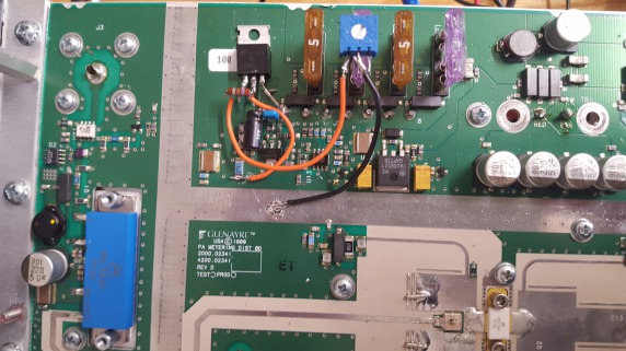
Now the hack. A more artful technician might have traced the bias supply to see how it was controlled. That's not me. I simply built up an LM317 adjustable power supply by super glued components to PC board and wired them together, cut the trace to the original bias supply, leaving in place the ferrite filer and ESD protection. I reconnected the bias (pin 2 on the MHL 9838). I also drilled a hole in amp enclosure so I reach the adjustment pot on the new LM317 bias supplycircuit.
RF input of 1/2 watt will drive the amp to its rated output of 25 watts and by incresing the bias well beyond (I quit at 40 watts). Output was still narrow and clean on the spectrum analyzer but I cut the bias back to keep from letting out the magic smoke that keeps them operating.
Haven't put it on the air yet. 900 MHz transverter in another of the projects now released from the closet and nearing completion but I'll post an update soon if the weather remains cold and the outside world satys outside.
Pictures below. Gl-T8200 docs and MHL 9838 datasheet on Links page.
W8BL

